Feedback amplifier is a type of amplifier whose feedback exists between the output and input signal. The concept of feeding the output signal back to its input circuit is known as feedback and that is why it is known as a feedback amplifier. It is dependent between the output and input with effective control. Feedback amplifiers are divided into two types: positive feedback and negative feedback.
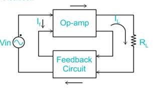
Below is a pictorial representation showing how feedback is implemented.
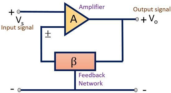
As we know that an amplifier is a device that amplifies the signal. When we talk about an ideal amplifier, there exist some important characteristics like voltage gain, input impedance, output impedance, bandwidth etc. These parameters of an amplifier are controlled by employing a feedback network. Thus, a feedback network is employed in an amplifier so as to control the gain and other factors of the device.
Feedback amplifiers are basically classified into 2 categories:
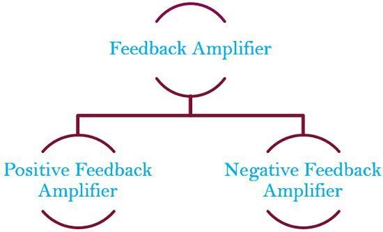
Positive Feedback Amplifier: Thisis a type of an amplifier in which source signal and the feedback signal are in the same phase. Thus, the feedback signal applied increases the strength of the input signal.

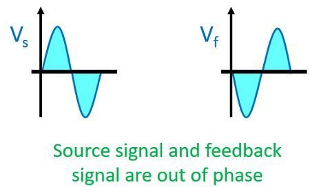
Negative Feedback Amplifier: In this type of amplifier source signal and the feedback signal are out of phase with each other. Thus, the feedback signal applied to decrease the strength of the input signal. Negative feedback reduces gain of the amplifier. It also reduces distortion, noise and instability. This feedback increases bandwidth and improves input and output impedances. Due to these advantages, the negative feedback is frequently used in amplifiers.
Negative feedback is frequently used in amplifier circuits as positive feedback causes excessive distortion in the circuit which we will discuss later.
Concept of Feedback
The figure shown below represents the block diagram of an amplifier employing feedback network:
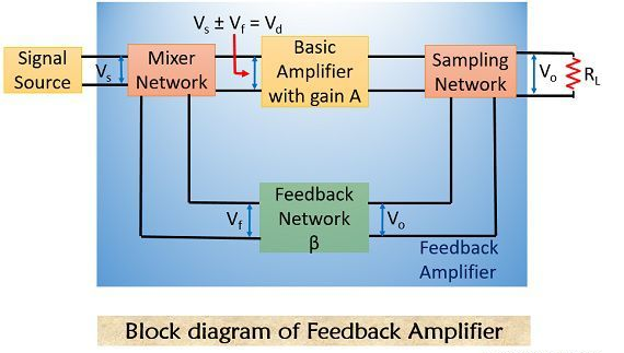
The various blocks of the feedback amplifier section are discussed below:
- Signal Source: The signal source can be a voltage source Vs in series with resistor Rs or it can be a current source Is with parallel resistor Rs.
- Feedback network: A feedback network is a linear two-port network that contains resistors, inductors, capacitors. Its function is to fed back some portion of output to the input.
- Sampling Network: These are basically of two types, current sampling network and voltage sampling network. The output voltage is sampled when we connect feedback network in either shunt or in series with the output.
- Mixer: Mixer circuit is also known as the comparator; it can be a series mixer or shunt mixer. It mixes the source signal and feedback signal thus produces positive or negative feedback for the device.
Operation of Feedback Amplifier
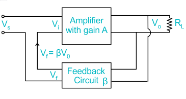
Let us have a look at the diagram shown below:
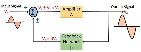
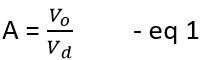
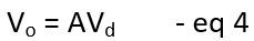
Here, we are talking about the general condition in which we are providing feedback to the input. It can be positive feedback or a negative one. An input signal Vs is applied to the amplifier with gain A, that produces an amplified signal, Vo. A portion or fraction of this Vo is then fed to a feedback network having gain β. The output of feedback network is Vf, this signal is then given to summer or a mixer that resultantly produces eithersum or difference of the two-signal depending on their phase relationship. The gain of an amplifier is given as the ratio of output voltage or current to the input voltage or current. So for the above figure, the gain of the circuit without feedback is given as:
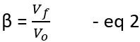
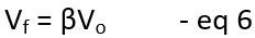
The gain of feedback network is given as:
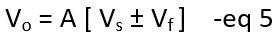
But as we can see Vd is the mixer output voltage given by
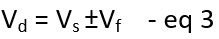
The signal voltage Vs and mixer output voltage Vd will only be equal in a feedback amplifier unless the output is not generated.
From Eq 1 we can write as
Substituting the value Vd in eq 4
From Eq 2
Substituting the value of Vf in eq 5

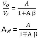
where,

Feedback Amplifier Topologies
There are four types of feedback topology
- Current series feedback amplifier
- Voltage series feedback amplifier
- Current shunt feedback amplifier
- Voltage shunt feedback amplifier
Current series feedback amplifier
In this feedback amplifier, both the input and output impedance are increased. The feedback circuit is placed in series with the input and output. Here a fraction of the output voltage is applied in series with the input voltage in the feedback circuit.
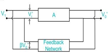
Voltage series feedback amplifier
The feedback circuit is connected in shunt with the output in such a way that it decreases the output impedance and increases the input impedance. In this circuit, it is placed in a shunt with the output but in series with respect to the input signal.
Current shunt feedback amplifier
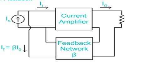
It increases the output impedance and because of connecting the feedback circuit in parallel with the input, the input impedance is decreased. Here, the feedback circuit is placed in series with the output and in parallel with the input.
Voltage shunt feedback amplifier
Here the feedback circuit is placed in a shunt with respect to output and input as well. It decreases the input and output impedance.
Worked Example 1
If the input impedance and the voltage gain of an open loop voltage series feedback amplifiers are 3kΩ and 100 and the feedback factor is . What is the impedance of the close loop configuration?
Solution
A = 100, Rin = 3 kΩ
Noted that
Rinf = Rin (1+ Aβ) = 3 kΩ (1+100) = 9 kΩ
Worked Example 2
Consider a common-emitter amplifier with negative voltage feedback. The open-loop gain (A) is 100, and the feedback factor (β) is 0.05. Calculate the closed-loop gain (Af).
Solution:
Using the formula Af = A / (1 + βA), we have:
Af = 100 / (1 + 0.05 x100) = 100 / 6 = 16.67