As the world continues to push the boundaries of data transmission, speed, and efficiency, the infrastructure supporting these advancements becomes increasingly critical. At the heart of modern optical networks lies a range of passive components, one of which plays a vital role in power distribution and signal routing—the fused coupler. Compact, reliable, and cost-effective, this component helps define the performance and architecture of contemporary fiber optic systems.
This article explores what a fused coupler is, how it functions, its types, applications, benefits, and why it’s a cornerstone in optical communication networks and fiber-based technologies.
What Is a Fused Coupler?
A fused coupler is a passive fiber optic device that splits or combines optical signals between two or more optical fibers. It is created by fusing and tapering two (or more) optical fibers together under controlled heat and tension. The process results in a shared core region where light can transfer from one fiber to another via evanescent field coupling.
Fused couplers are used for power splitting, signal tapping, wavelength routing, and other essential operations in optical communication and sensing systems. Their popularity stems from their low insertion loss, minimal back reflection, high reliability, and compatibility with a wide range of fiber types.
How Does a Fused Coupler Work?
The operation of a fused coupler is based on the principle of evanescent wave coupling. Here’s how it works in simple terms:
- Fusion Process: Two or more optical fibers are aligned side-by-side and heated while being pulled, creating a taper where the fiber cores come close enough to allow their evanescent fields to overlap.
- Coupling Region: In the tapered region, some portion of the optical power in one fiber leaks into the adjacent fiber due to the overlapping of the light fields.
- Power Splitting or Combining: The result is a device that can either split the input signal into two or more outputs (splitting) or combine two signals into one output (combining).
The ratio of power distribution between the outputs is defined during the manufacturing process and can vary depending on the coupler design. Common splitting ratios include 50:50, 90:10, 70:30, and more.
Types of Fused Couplers
Fused couplers come in a variety of configurations tailored to different applications. Some common types include:
1. 2×2 Coupler
This type has two input and two output ports. Light entering any input port is divided between both output ports. 2×2 couplers are used in bidirectional systems or optical switches.
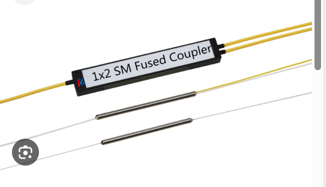
2. 1×2 Coupler (Splitter)
A signal from one input fiber is split into two outputs. This is commonly used for signal monitoring or passive splitting in FTTH (Fiber to the Home) networks.
3. Wavelength Division Multiplexer (WDM) Coupler
This version selectively combines or separates different wavelengths. For instance, it may combine 1310 nm and 1550 nm signals onto one fiber.
4. Polarization Maintaining (PM) Coupler
Built using polarization-maintaining fibers, this coupler retains the polarization of light and is used in applications where polarization integrity is essential.
5. Star and Tree Couplers
These are multiple input/output devices used for signal distribution in complex network topologies, often in data centers or sensor networks.
Applications of Fused Couplers
The fused coupler versatility and simplicity make it valuable in a wide variety of optical systems. Here are some of its most impactful applications:
1. Optical Communication Systems
In telecom and data networks, fused couplers are used for signal routing, tapping, and distribution. They play a critical role in passive optical networks (PONs), allowing service providers to split a single fiber into multiple connections.
2. Fiber Optic Sensors
Fused couplers enable interferometric configurations (like Mach-Zehnder and Michelson interferometers), used in sensing applications for strain, temperature, pressure, and vibration detection.
3. Optical Power Monitoring
By tapping a small percentage of the light using a fused coupler, network administrators can monitor signal levels without interrupting the main data flow.
4. Laser Systems
Couplers can combine outputs from multiple laser sources or split a laser signal for multiple simultaneous tasks, such as medical imaging or materials processing.
5. Test and Measurement Equipment
Engineers use fused couplers in laboratory setups to analyze optical performance, monitor network behavior, and prototype fiber-based systems.
Advantages of Using a Fused Coupler
The fused coupler remains popular among designers and engineers due to several notable benefits:
- Low Insertion Loss: Efficient transfer of optical signals with minimal loss.
- Broad Wavelength Range: Supports operation across a wide spectrum (e.g., 850 nm, 1310 nm, 1550 nm).
- Compact and Lightweight: Small form factor allows easy integration into complex systems.
- Stable and Passive: No electrical power is required; performance is stable over time.
- Customizable Split Ratios: Tailored designs for various signal routing needs.
These advantages make fused couplers not only reliable but also cost-effective for large-scale deployment in communication and sensing systems.
Challenges and Limitations
While highly useful, fused couplers are not without limitations:
- Fixed Splitting Ratio: Once manufactured, the split ratio cannot be adjusted, unlike variable optical couplers.
- Sensitive to Bending: Excessive bending of fiber near the coupling region can cause signal degradation.
- Environmental Sensitivity: Changes in temperature or humidity may affect coupling efficiency in non-hermetic designs.
- Limited Polarization Control: Standard fused couplers do not maintain polarization unless specifically designed as PM versions.
Despite these challenges, careful installation and proper design considerations can mitigate most issues, ensuring long-term performance.
Manufacturing Process of a Fused Coupler
Producing a high-quality fused coupler requires precision and expertise. The general process includes:
- Fiber Preparation: Stripping and cleaning the fiber coating.
- Alignment: Placing two or more fibers side-by-side under a microscope.
- Fusion and Tapering: Applying heat while pulling the fibers to create a uniform coupling region.
- Encapsulation: Housing the fused region in a protective sleeve or case to prevent damage.
- Testing: Measuring insertion loss, return loss, and coupling ratio for quality assurance.
This process demands advanced equipment, controlled environments, and skilled operators to maintain consistency across production batches.
The Future of Fused Coupler Technology
As fiber optic networks expand with the rise of 5G, IoT, cloud computing, and smart infrastructure, demand for passive optical components like the fused coupler will continue to rise. Emerging developments include:
- Miniaturization: Smaller couplers for compact devices and photonic integrated circuits.
- Expanded Wavelength Operation: New materials to support mid-infrared and visible wavelength applications.
- Automation in Production: Precision robotic fusion for high-yield, consistent manufacturing.
- Enhanced Durability: Ruggedized couplers for use in aerospace, military, and outdoor sensing applications.
The role of fused couplers will grow beyond traditional telecom into areas like autonomous vehicles, biomedical devices, and industrial automation.
Conclusion
The fused coupler is a foundational component of today’s optical infrastructure. Its simplicity, reliability, and effectiveness in splitting or combining light signals make it indispensable for communication networks, sensing applications, and optical laboratories. As data demands increase and optical systems grow in complexity, the fused coupler remains a quiet yet powerful enabler behind the scenes.
Whether you’re building a fiber-optic network, designing an interferometric sensor, or integrating photonics into a new product, understanding and using fused coupler technology is key to achieving precision, performance, and scalability.